Material
Other, Global universal model
Condition
Other, Global universal model
Task
Other, Global universal model
Mathematical Model
Other, Global universal model
Signal
Other, Global universal model
Customized
Non-Customized
Structure
Other, Global universal model
Operating temperature
-40 ℃ to 70℃
Dimensions
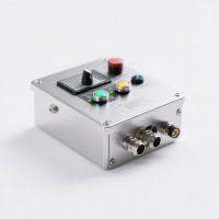
Approximately 100mm×150mm×50mm
Weight
Approximately 0.8kg
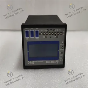
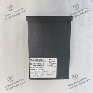
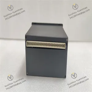
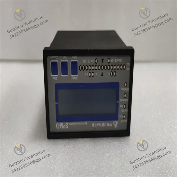
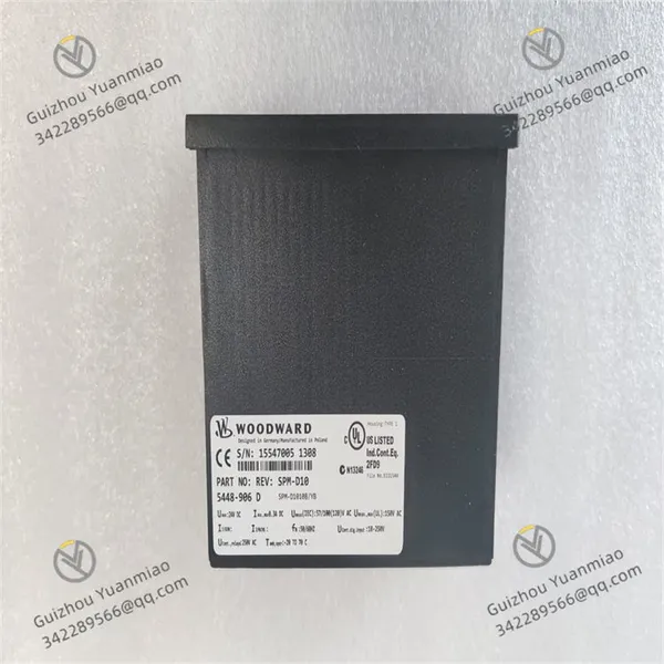
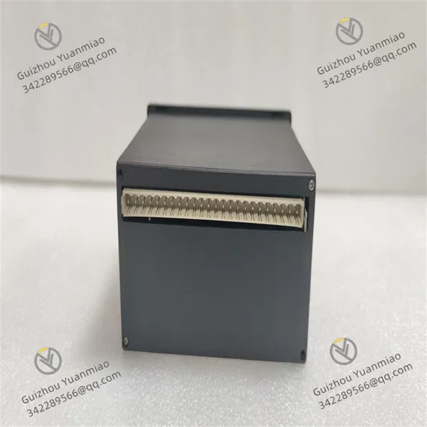
Woodward 5448-906
Application Scope
Suitable for various power equipment such as diesel engines, gas engines, steam turbines, or gas turbines. It is widely applied in generator sets, compressors, pump stations, ships, locomotives, etc., effectively ensuring stable equipment operation within set ranges.
Signal Input
Enables setting of equipment speed or load based on computer control signals, supporting multiple input signal types such as 4-20mA or 1-5Vdc, providing users with rich options to meet different control requirements.
Working Modes
Features two working modes: isochronous regulation and droop regulation.
Isochronous regulation is mainly used for constant speed control, suitable for single-unit operation or collaborative work of multiple prime movers in independent power grids.
Droop regulation provides a more flexible control method.
Functional Integration
Can work in conjunction with a range of Woodward equipment, such as automatic power transfer switches, input-output controllers, generator load controllers, etc., to achieve comprehensive system control. In addition to basic speed or load control functions, it also has rich additional functions such as synchronization or deceleration control, high-low speed adjustment, and fuel limit for overspeed starting, further enhancing its performance and application scope.
Output Signal
The controller provides high-precision output signals proportional to the fuel setting required to achieve the desired speed/load, ensuring precise control.
Durability
Designed to fully consider the complexity of industrial environments, it can stably operate within the temperature range of -20°C to 70°C, adapting to various harsh conditions.
Configuration and Protection
Belongs to the 3200XT-P1 version in Woodward's EasYgen 3000XT series, equipped with a monitor and designed for front-panel installation. Its toolkit software has multilingual functions, supporting 14 languages including English, French, German, and Japanese. The built-in Human-Machine Interface (HMI) features a color LCD screen and soft keys (now with dedicated buttons), enabling direct control of the 5448-906 device, and is equipped with multi-level password protection to prevent unauthorized changes. Additionally, this model has three freely configurable PID controllers, providing input and output control (kW and kvar), as well as synchronization (slip/phase matching) functions for Main Circuit Breakers (MCB) and Generator Circuit Breakers (GCB). The generator set has four operating modes and can be optionally configured with a manual circuit breaker control device.


Common Faults and Solutions for Woodward 5448-906I. Communication Faults
Fault Phenomenon
The device cannot communicate with the host computer (such as PLC, monitoring system), or data transmission is interrupted or lost.
The Ethernet port or RS-232 port indicator lights are off or flashing abnormally.
Possible Causes and Solutions
Hardware Connection Issues
Cause: Loose cables, oxidized interfaces, or damaged connectors.
Solution:
Check if both ends of the communication cable are tightly plugged, and replace with a spare cable for testing.
Wipe the port contacts with alcohol to remove oxidation; if the interface is damaged, contact maintenance or replace the module.
Parameter Configuration Errors
Cause: Parameters such as baud rate, data bits, stop bits, and parity do not match the host computer.
Solution:
Confirm communication parameters through device configuration software (such as AppManager) to match the host computer settings (e.g., baud rate 9600, 8 data bits, 1 stop bit, no parity).
Electromagnetic Interference
Cause: Communication cables are close to strong electromagnetic equipment (such as frequency converters, motors), causing signal distortion.
Solution:
II. Control Abnormalities (e.g., Speed Fluctuation, Regulation Failure)
Fault Phenomenon
The speed of the engine/turbine controlled by the device is unstable, or it cannot reach the set value.
Actuators (such as valves, oil pumps) act abnormally, unresponsive or misbehaving.
Possible Causes and Solutions
Sensor Faults
Cause: Abnormal signals from speed sensors (such as magnetoelectric, photoelectric types), or loose wiring.
Solution:
Use a multimeter to measure the sensor output signal (e.g., a magnetoelectric sensor should output an alternating voltage when rotating, with frequency proportional to speed). If the signal is missing or abnormal, replace the sensor.
Check the sensor cable connection to ensure the shield layer is well grounded.
Improper Parameter Settings
Cause: PID parameters (proportional, integral, derivative coefficients) are not optimized, or the control mode is set incorrectly.
Solution:
Re-initialize parameters with reference to the equipment manual, and gradually debug starting from default values (e.g., adjust the proportional coefficient first, then the integral time, and finally fine-tune the derivative coefficient).
For issues related to "isochronous regulation" or "droop regulation", check if the difference setting is reasonable (such as the current threshold for differential protection).
Actuator Faults
Cause: Hydraulic valve sticking, motor drive circuit damage, or poor relay contact.
Solution:
Manually test the actuator action (e.g., send open/close signals to the valve and observe the response). If sticking occurs, clean or replace components; if there is a circuit fault, check the drive board power supply and relay coil resistance (normal should be tens to hundreds of ohms).
III. Power Supply Faults
Fault Phenomenon
Possible Causes and Solutions
Abnormal Input Power Supply
Cause: Unstable voltage (e.g., 220V power fluctuates by more than ±10%), reverse polarity, or blown fuse.
Solution:
Use a multimeter to measure the input voltage. If it exceeds the rated range (refer to the equipment manual, typically DC 24V or AC 220V), install a voltage stabilizer or check the power supply circuit.
Open the module casing, check if the internal fuse is blown (glass tube fuse can be visually judged), and replace it with the same Specification (note: power off before operation).
Power Module Damage
Cause: Aging or short circuit of internal power chips and capacitors.
Solution:
IV. Alarm Faults (e.g., Overload, Overspeed)
Fault Phenomenon
Possible Causes and Solutions
Actual Working Conditions Exceed Limits
Cause: The actual speed of the controlled equipment (such as an engine) exceeds the set overspeed threshold, or excessive load causes current to exceed the limit.
Solution:
Immediately stop the machine to check the equipment working conditions, and eliminate issues such as mechanical jamming or excessive load (e.g., whether the steam turbine inlet steam volume is too large, or the engine load suddenly increases).
Reset the protection threshold through configuration software (must comply with equipment safety specifications, e.g., set the overspeed trip threshold to 110% of the rated speed).
False Alarms in Detection Circuits
Cause: Sensor signal drift, or incorrect setting of the current transformer ratio for differential protection.
Solution:
Calibrate the sensor (e.g., compare the speed sensor with a tachometer). If the signal drifts severely, replace the sensor.
Check if the wiring of the current transformer for differential protection is correct (whether the end with the same name is consistent), and if the ratio parameter matches the actual value (e.g., CT ratio 1000/5A, which needs to be set to 200 in the software).