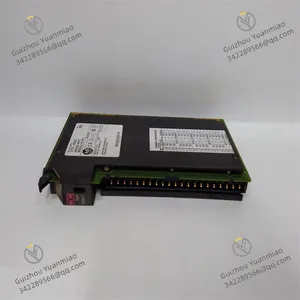
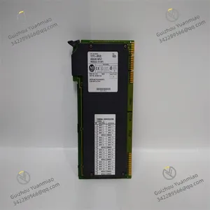
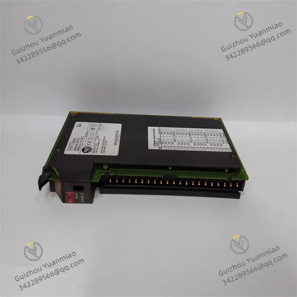
I. Product Overview
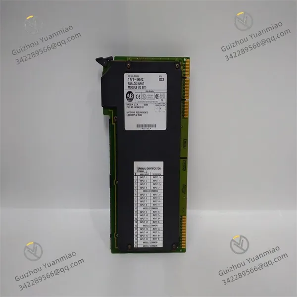
The Allen-Bradley 1771-IFE module is a high-performance analog input module in the PLC-5 series, mainly used for the precise collection and conversion of various on-site analog signals in industrial automation systems. In the industrial production process, non-electrical physical quantities such as temperature, pressure, flow, and liquid level are usually converted into analog electrical signals through sensors, and these signals are key parameters reflecting the state of the production process. The 1771-IFE module can convert these continuously changing analog signals into digital signals recognizable by the PLC controller, providing reliable original data for the system to achieve precise control, process optimization, and fault diagnosis.
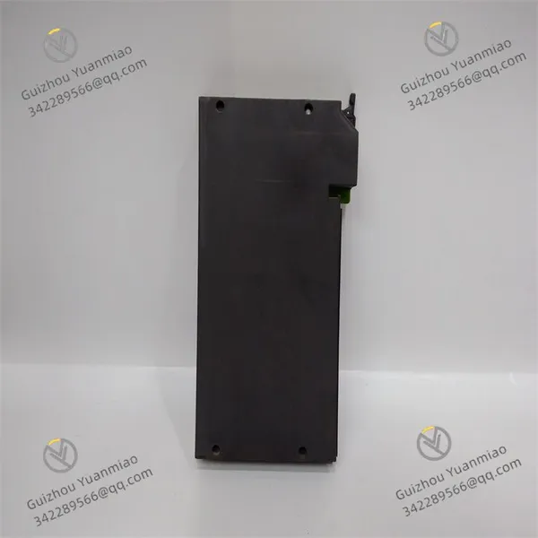
The module adopts a compact design, with dimensions perfectly matching the 1771 series I/O enclosures, and can be conveniently installed in industrial control cabinets, saving installation space. The shell is made of high-strength industrial-grade materials, which have undergone strict environmental tolerance tests, and have excellent anti-vibration and anti-impact performance. It can operate stably in environments with continuous vibration and impact such as mechanical processing workshops and chemical production equipment. At the same time, its shell has good dust-proof and moisture-proof performance, and can adapt to the dusty and humid complex environment of industrial sites, ensuring stable signal collection performance under various harsh conditions.

II. Performance Parameters
(1) Electrical Characteristics
Power Requirement: The working power of the 1771-IFE module is taken from the backplane of the 1771 I/O enclosure, requiring two types of power supplies: +5V DC and +24V DC. Among them, +5V DC supplies power to the internal logic circuit of the module, with typical current consumption within a specific range; +24V DC mainly provides excitation power for external sensors, and the current consumption varies according to the number and type of connected sensors. This dual-power design not only ensures the stable operation of the internal circuit of the module but also provides a reliable working power supply for external sensors, simplifying the power supply configuration of the system.
Input Channels: The module is usually equipped with 8 independent analog input channels, each of which can independently collect analog signals, meeting the needs of small and medium-sized industrial control systems for multi-parameter parallel monitoring and improving the integration of the system.
Input Signal Types: It supports various types of analog input signals, including DC current signals (such as 4-20mA) and DC voltage signals (such as 0-10V, ±5V, etc.). Through software configuration, the signal type of each channel can be flexibly selected, and it is compatible with temperature sensor signals such as thermocouples and thermal resistors, with strong versatility.
Resolution: The resolution of the module is usually 12 bits, which can convert analog signals into digital quantities ranging from 0 to 4095, ensuring accurate capture of small signal changes and meeting the needs of high-precision measurement. For example, for a 4-20mA current signal, its minimum resolution can reach about 3.9μA, which can accurately reflect the slight fluctuations of the signal.
Accuracy: Within the standard operating temperature range, the conversion accuracy of the module is usually better than ±0.1% of the full scale, ensuring the accuracy of the collected data and providing a reliable basis for the precise control of the production process.
(2) Interface Characteristics
External Signal Interface: Equipped with a standard terminal block for connecting external sensors or transmitters. The terminal block adopts a screw fixing method, so the wiring is firm and reliable, which can effectively prevent wiring looseness caused by vibration and other factors, ensuring the stability of signal transmission. The interface is clearly marked, clearly distinguishing the input terminals and power terminals of different channels, which is convenient for technicians to complete wiring operations quickly and accurately.
Backplane Communication Interface: It communicates with the PLC processor through the backplane connector of the 1771 I/O enclosure to realize the transmission of the converted digital signals to the PLC controller. The backplane interface adopts a high-speed data transmission method to ensure that the conversion results of analog signals can be transmitted to the PLC in real time, meeting the real-time requirements of the system.
(3) Environmental Adaptability
Operating Temperature: It can work stably within a temperature range of 0°C to 60°C (32°F to 140°F), and can adapt to common temperature changes in industrial production workshops. Whether it is a high-temperature metallurgical environment or a slightly lower-temperature chemical workshop, it will not affect its conversion accuracy and working stability.
Storage Temperature: In the storage state, it can withstand extreme temperatures from -40°C to 85°C (-40°F to 185°F), ensuring that the internal components of the module will not be damaged even in harsh temperature conditions during transportation, storage and other links, thus guaranteeing the performance reliability of the module.
Anti-Electromagnetic Interference: It meets industrial-grade electromagnetic compatibility standards and has strong anti-electromagnetic interference capabilities. It can effectively resist electromagnetic interference generated by equipment such as motors, frequency converters, and electric welders in industrial sites, preventing analog signals from being interfered with and causing distortion, and ensuring the accuracy of converted data.
III. Functional Characteristics
(1) High-Precision Signal Conversion
The core function of the 1771-IFE module is to realize high-precision conversion of analog signals. It has a built-in high-performance A/D converter, which can accurately convert the externally input continuous analog signals into discrete digital signals and transmit them to the PLC controller through the backplane interface. Whether it is a slowly changing temperature signal or a rapidly fluctuating pressure signal, the module can accurately capture them with minimal conversion error, providing high-quality data support for the precise control of the system. For example, in the temperature control of a chemical reaction kettle, the module can accurately convert the temperature signal collected by the thermocouple into a digital quantity, and the PLC precisely adjusts the heating device according to this data to ensure that the reaction temperature is stable within the set range.
(2) Independent Channel Configuration
The module supports independent configuration of each input channel. Users can set different signal types, range ranges, and filtering parameters for different channels through PLC programming software. This flexible configuration method enables the module to connect multiple different types of sensors at the same time, meeting the needs of monitoring multiple parameters in industrial sites and improving the versatility and applicability of the module. For example, in a production line, temperature, pressure, and flow signals can be collected through different channels, and each channel is individually configured according to the corresponding sensor type.
(3) Filtering Function
The 1771-IFE module has a digital filtering function. Users can set appropriate filtering parameters according to the characteristics of on-site signals, effectively suppressing high-frequency noise and interference in the signals, and making the converted digital signals more stable. For industrial environments with more electromagnetic interference, the filtering function can significantly improve the signal-to-noise ratio of the signal and ensure the stability of the collected data. For example, when collecting pressure signals near the motor, the filtering function of the module can effectively filter out the electromagnetic interference generated by the motor, avoiding signal fluctuations from affecting the control accuracy.
(4) Diagnosis and Status Indication
The module is equipped with status indicators, including a power indicator and channel status indicators. The power indicator being on indicates that the module is powered normally; the channel status indicator can reflect the working status of the corresponding channel, such as whether the signal is input normally, whether there is a fault, etc. In addition, the module can also send diagnostic information such as power failure, channel overload, and A/D conversion error to the PLC controller through the backplane interface, facilitating maintenance personnel to timely detect and eliminate faults and improving the maintainability of the system.
(5) Sensor Excitation Power Supply
The module has a built-in +24V DC excitation power supply, which can provide working power for external two-wire or four-wire transmitters, eliminating the need for an additional independent power module, simplifying the system's wiring and power supply design, and reducing the overall cost. The excitation power supply has an overcurrent protection function. When a short circuit occurs in the external circuit, it can automatically cut off the output to prevent damage to the module and improve the safety of the system.
IV. Installation and Use
(1) Installation Steps
Preparation before Installation: Before installation, check whether the appearance of the module is intact, whether there is damage or deformation, and confirm that components such as the terminal block are not loose. At the same time, ensure that the installation environment meets the working requirements of the module, away from strong electromagnetic interference sources, high-temperature heat sources, and corrosive substances. Prepare necessary installation tools, such as screwdrivers and wire strippers, and disconnect the power supply of the 1771 I/O enclosure to ensure the safety of the installation process.
Determine the Installation Position: The 1771-IFE module should be installed in the idle slot of the 1771 I/O enclosure. The installation position should be convenient for observing the status of the indicators and performing wiring operations, and at the same time, ensure good ventilation in the enclosure to facilitate heat dissipation of the module. During installation, follow the module installation sequence of the enclosure to ensure that the module is accurately docked with the enclosure backplane connector.
Module Fixing: Align the module with the guide rails and slots in the enclosure, push it in smoothly until the module is in close contact with the backplane connector, then use screws to fix the module on the enclosure to prevent the module from loosening due to vibration during equipment operation, which may affect the stability of the electrical connection.
External Wiring: According to the system design drawings, connect the signal lines of external sensors or transmitters to the terminal block of the module. When wiring, pay attention to distinguishing the signal type and positive and negative polarities, connect correctly according to the terminal marks, and ensure that the wiring is firm and reliable to avoid virtual connection. For sensors that require an excitation power supply, correctly connect the +24V DC power supply provided by the module.
Installation Inspection: After the installation is completed, carefully check the fixing of the module and whether the external wiring is correct. After confirmation, power on the 1771 I/O enclosure and observe whether the power indicator of the module is on. If it is on, it indicates that the module is powered normally.
(2) Usage Methods
Parameter Configuration: Configure the parameters of the 1771-IFE module through PLC programming software (such as RSLogix 5), including the signal type, range range, filtering parameters, module address, etc. of each channel. During configuration, settings should be made according to the type of connected sensor and on-site requirements to ensure that the module can accurately collect signals.
Program Writing and Debugging: Write programs in the PLC programming software to read and process the digital signals converted by the module. After the program is written, download it to the PLC controller for debugging. During debugging, by changing on-site parameters (such as adjusting temperature, pressure, etc.), observe whether the corresponding channel status indicator of the module changes normally and whether the PLC can correctly read the signal. If there is any abnormality, timely check the wiring and parameter configuration and make adjustments.
Daily Monitoring and Maintenance: During the operation of the system, operators can real-time monitor the various parameter values collected by the module through the PLC's human-machine interface (HMI) or monitoring software. Maintain the module regularly, including cleaning dust on the surface of the module, checking whether the wiring is loose, and observing whether the indicator status is normal, to ensure the long-term stable operation of the module. If a fault is found in the module, it should be repaired or replaced in a timely manner to avoid affecting the normal operation of the system.


 Contact Platform Support
 Help Center