Material
Other, Global universal model
Condition
Other, Global universal model
Task
Other, Global universal model
Mathematical Model
Other, Global universal model
Signal
Other, Global universal model
Customized
Non-Customized
Structure
Other, Global universal model
Operating Temperature
0℃~60℃
Relative Humidity
5%-95% (non-condensing)
Dimensions
210mm × 80mm × 80mm
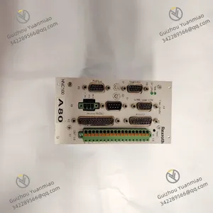
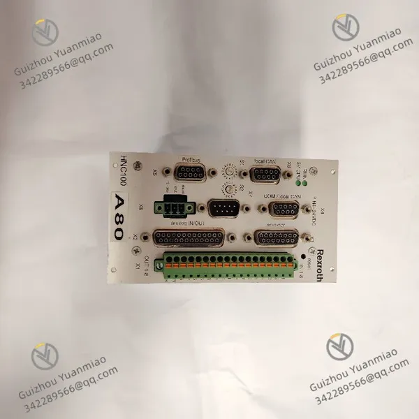
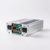
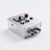
The REXROTH VT-VSPA1-1-11 is a control module. With its precise current regulation capability, flexible parameter configuration function, and reliable anti-interference design, it is widely used in fields such as machine tool manufacturing, construction machinery, metallurgical equipment, injection molding, and marine hydraulics. It undertakes the tasks of electrical signal amplification and precise control for electro-hydraulic proportional pressure valves, flow valves, and directional valves. Its core technical advantages lie in the adoption of a closed-loop feedback regulation architecture and modular design. It can output high-precision proportional control current, realizing continuous stepless regulation of parameters such as flow rate, pressure, and speed of hydraulic actuators. It is seamlessly compatible with all types of Rexroth electro-hydraulic proportional valves, constructing a closed-loop control chain of "electrical signal input - precise amplification - hydraulic execution - status feedback". It provides stable and reliable core support for high-precision hydraulic control of industrial equipment and is a benchmark control component in mid-to-high-end electro-hydraulic proportional control systems.
Technical Parameters
1.1 Core Control Parameters
Adopts a high-precision closed-loop current regulation mode. The output current range is 4mA~20mA DC (standard mode) and 0mA~20mA DC (optional mode), with a continuous regulation accuracy of ±0.1mA.
The current regulation response time is ≤1ms (step signal from 5% to 95%), ensuring fast tracking of control signals.
Equipped with a current ramp regulation function, the ramp up/down time is continuously adjustable from 0.1s to 10s, which can effectively suppress hydraulic shock.
Supports independent control of 1 proportional valve, compatible with single-coil electro-hydraulic proportional valves.
1.2 Input and Output Parameters
Analog input supports three signal types: 0V~10V DC, ±10V DC, and 4mA~20mA DC. The input impedance is ≥100kΩ (for voltage signals) and ≤100Ω (for current signals).
Equipped with 1 feedback signal input interface, supporting 0V~10V DC or 4mA~20mA DC feedback signal acquisition for forming closed-loop control.
The output terminal has an overcurrent protection function. The maximum output current is 3A (instantaneous) and 1.5A (continuous), and the protection threshold can be configured via parameters.
Equipped with 2 digital inputs (PNP/NPN optional) for control signal enable, ramp function start/stop, etc., with a response time of ≤0.1ms.
1 digital output for fault alarm or status feedback.
1.3 Anti-Interference and Protection Parameters
Adopts a photoelectric isolation design. The isolation voltage between input and output signals is ≥250V AC (50Hz, lasting for 1 minute), and the isolation resistance is ≥1000MΩ (500V DC).
Common-mode rejection ratio (CMRR) ≥80dB (50Hz/60Hz), differential-mode rejection ratio (DMRR) ≥60dB.
Built-in RC filter circuit and transient voltage suppressor (TVS) diode, which can effectively suppress high-frequency interference and surge impact.
Electromagnetic compatibility complies with EN 55011 Class A, IEC 61000-4-2 (ESD), and IEC 61000-4-3 (RS) standards. The anti-static interference capability is ≥8kV (contact discharge) and 15kV (air discharge), and the anti-RF interference capability is ≥30V/m (80MHz~2GHz).
Protection class: IP20 (modular type), suitable for installation in control cabinets.
1.4 Power Supply and Power Consumption Parameters
Powered by a single 24V DC power supply. The input voltage range is 18V DC~30V DC, with a typical input of 24V DC.
The module's static power consumption is ≤5W, and the full-load operation power consumption is ≤15W (when outputting 1.5A).
Equipped with power reverse connection protection (no damage at ≤30V DC) and overvoltage protection (automatic output cutoff at ≥32V DC) to ensure power supply safety.
1.5 Environmental and Reliability Parameters
Operating temperature range: 0℃~60℃; storage temperature range: -20℃~80℃.
Relative humidity: 10%~90% (no condensation).
Vibration resistance complies with IEC 60068-2-6 standard (10Hz~500Hz, acceleration 5g); shock resistance complies with IEC 60068-2-27 standard (15g, 11ms half-sine wave).
Mean Time Between Failures (MTBF) ≥1,000,000 hours, supporting 24/7 continuous operation.
Functional Features
2.1 Closed-Loop High-Precision Current Regulation, Leading Control Accuracy in the Industry
Adopts a closed-loop control architecture of "command signal - current detection - error correction". A built-in high-precision current sensor collects the output current in real time, and dynamic error correction is performed through the PID regulation algorithm, achieving a regulation accuracy of ±0.1mA. It can precisely control the spool displacement of the proportional valve, ensuring that the control error of hydraulic system pressure or flow rate is ≤1%.
With a fast response time of 1ms, it can quickly track changes in input commands, adapting to the dynamic regulation needs of hydraulic systems, such as real-time fine-tuning of machine tool spindle speed and precise control of injection molding machine clamping force.
The current ramp regulation function can set a smooth current change curve according to working conditions, effectively avoiding shocks during hydraulic system startup or load switching and extending the service life of equipment.
2.2 Multi-Type Signal Compatibility, Flexible and Efficient System Integration
Supports input of 0V~10V, ±10V voltage signals, and 4mA~20mA current signals. It can be directly connected to various upper-level control devices such as PLCs, DCSs, and motion controllers without additional signal conversion modules, simplifying system integration.
Equipped with a feedback signal acquisition interface, it can access signals from proportional valve spool position sensors or hydraulic system pressure/flow sensors to form a closed-loop control loop, further improving the system's control accuracy.
Digital input/output interfaces enable logical interaction with the upper-level system, such as starting proportional valve control through digital input and feeding back the module's operating status through digital output, adapting to complex control logic scenarios.
2.3 Multiple Anti-Interference Protections, Stable Operation in Complex Environments
The input and output signals adopt a photoelectric isolation design, which completely cuts off the transmission path of external interference signals and solves the problem of ground loop interference in industrial sites.
The built-in RC filter circuit can filter out high-frequency noise, and the transient voltage suppressor diode can absorb surge impacts on the power supply or signal lines, effectively resisting the influence of strong interference sources such as frequency converters and motors.
The module housing adopts an electromagnetic shielding design, reducing the interference of external electromagnetic radiation on internal circuits. It ensures stable output of control current even in strong interference environments such as construction machinery and metallurgical workshops, with control signal fluctuation ≤0.05mA.
2.4 Intelligent Diagnosis and Protection, Significantly Improved Operation and Maintenance Efficiency
Equipped with a comprehensive fault diagnosis function, it can real-time monitor faults such as output overcurrent, power overvoltage/undervoltage, module overheating, and abnormal feedback signals. It sends fault alarm signals through the digital output interface, and at the same time, the LED indicators on the module panel (power light, operation light, fault light) intuitively display the operating status, allowing operation and maintenance personnel to quickly locate the fault type.
The overcurrent protection function at the output terminal can automatically limit the current when the load is short-circuited or the proportional valve coil fails, avoiding module damage.
It supports reading fault logs through dedicated debugging software, recording information such as fault occurrence time and fault type, providing data support for fault troubleshooting.
2.5 Modular Design with Strong Compatibility, Convenient Installation and Maintenance
Adopts a standardized modular design, with a compact size (45mm in width × 100mm in height × 150mm in depth). It supports installation on standard 35mm DIN rails, with high space utilization in the control cabinet.
The terminals adopt a plug-in design, facilitating quick wiring and maintenance.
Supports on-site parameter configuration. Key parameters such as output current zero point, gain, and ramp time can be quickly set through the adjustment knobs on the module, and refined parameter configuration and storage can also be performed through dedicated software.
It is seamlessly compatible with Rexroth's full range of electro-hydraulic proportional valves (such as 4WRPEH series proportional directional valves and DBET series proportional pressure valves), and can be put into use without additional debugging, shortening the system debugging cycle.

Working Principle
3.1 Signal Reception and Preprocessing
The analog control signal (e.g., 4mA~20mA) output by the upper-level control device (such as a PLC) is connected to the module through the input terminal and first enters the signal preprocessing unit.
The voltage signal undergoes impedance matching through a high-impedance buffer to avoid signal attenuation.
The current signal is converted into a voltage signal through a precision shunt resistor.
The preprocessed signal passes through an RC filter circuit to filter out high-frequency noise, ensuring the stability of the input signal.
At the same time, the digital input signal (such as an enable signal) is sent to the control unit after photoelectric isolation to trigger the corresponding control logic.
3.2 Signal Processing and Command Conversion
The preprocessed analog signal is sent to the core control unit (using a high-performance microprocessor). The control unit converts the input signal into a corresponding target output current command according to the preset gain parameters.
If the ramp regulation function is enabled, the control unit generates a smooth current command curve according to the set ramp time to avoid step changes in current.
The control unit also receives digital input signals to determine whether to start the output and whether to enable the ramp function, realizing the coordination of logical control and analog control.
3.3 Current Amplification and Output
The current command generated by the control unit is sent to the power amplification unit. The power amplification circuit adopts a linear amplification circuit composed of MOSFET power tubes, amplifying the weak command signal into a large current (4mA~20mA) that can drive the proportional valve coil.
The power amplification unit has a temperature compensation function, which can dynamically adjust the amplification factor according to the ambient temperature to avoid output current drift caused by temperature changes.
The amplified current is transmitted to the electro-hydraulic proportional valve coil through the output terminal, driving the spool to displace, thereby controlling the pressure or flow rate of the hydraulic system.
3.4 Closed-Loop Feedback Regulation
To ensure the accuracy of the output current, the module has a built-in high-precision current sensor that collects the actual current signal at the output terminal in real time. The collected current signal is converted into a standard voltage signal after signal conditioning and fed back to the control unit.
The control unit compares the actual output current with the target current command, calculates the error value, and dynamically corrects the output of the power amplification unit through the PID regulation algorithm, so that the actual output current always tracks the target command, realizing closed-loop precise control.
If an external feedback signal (such as a spool position sensor signal) is connected, the control unit will further correct the output current based on this signal, improving the overall control accuracy of the system.
3.5 Fault Diagnosis and Protection
The fault diagnosis unit monitors the status of each key node of the module in real time, including input power voltage, output current magnitude, internal module temperature, and feedback signal integrity.
If faults such as power voltage lower than 18V or higher than 30V, output current continuously exceeding 1.5A, internal module temperature ≥70℃, or loss of feedback signal are detected, the diagnosis unit immediately sends a fault signal to the control unit.
After receiving the fault signal, the control unit immediately cuts off the output or limits the output current, sends an alarm signal through the digital output interface, and at the same time activates the fault indicator light on the panel to record fault information.
Common Faults and Solutions
4.1 Fault 1: No Response of Output Current, Proportional Valve Not Operating
Possible Causes
Abnormal power supply.
Missing or incorrect input control signal.
Module enable signal not connected.
Loose or short-circuited wiring at the output terminal.
Fault in the internal power amplification circuit of the module.
Solutions
Use a multimeter to measure the module's power input voltage, ensuring it is within the range of 18V~30V. If the voltage is abnormal, check the power module or power supply line.
Use an oscilloscope or multimeter to detect the input control signal, confirming that the signal type is compatible with the module (e.g., 0V~10V) and the signal amplitude is normal. If the signal is abnormal, check the upper-level control device or signal cable.
Check the digital enable signal to ensure it is valid (the PNP/NPN signal type is consistent with the module configuration). If it is not connected, check the enable signal line.
Check the wiring of the output terminal, reinsert and fasten it. Use a multimeter to measure the line continuity, replace damaged cables, and check for short-circuit issues in the proportional valve coil (the coil resistance should meet the technical requirements of the proportional valve).
Replace with a spare module for testing. If the fault disappears, the power amplification circuit of the original module is faulty and needs to be repaired or replaced.
4.2 Fault 2: Decreased Output Current Accuracy, Large Fluctuations in Hydraulic Parameters
Possible Causes
Drift of current zero point or gain parameters.
Fault in the closed-loop feedback circuit.
Severe external interference.
Poor module grounding.
Excessively high ambient temperature.
Solutions
Re-calibrate the output current zero point and gain through the module's adjustment knobs or dedicated software, and verify the output accuracy after calibration.
Check the feedback signal line to ensure firm wiring. Use a multimeter to measure the feedback resistance value. If it is abnormal, replace the feedback sensor or line.
Detect on-site interference sources, adjust the distance between the module and frequency converters/high-voltage cables to ≥1.5m, replace the signal cable with a double-shielded cable, and ground it at one end (ground resistance ≤4Ω).
Check the module's grounding terminal to ensure reliable grounding. Adopt an independent grounding method and avoid sharing it with power grounding.
Check the module's operating ambient temperature. If it is ≥50℃, clean the dust in the heat dissipation holes of the control cabinet and install a cooling fan to ensure the ambient temperature ≤40℃.
4.3 Fault 3: Module Fault Indicator Light Always On, Output Interrupted
Possible Causes
Output overcurrent (short-circuit of the proportional valve coil).
Power overvoltage/undervoltage.
Module overheating.
Abnormal feedback signal.
Fault in the internal circuit of the module.
Solutions
Disconnect the wiring of the proportional valve coil, use a multimeter to measure the coil resistance. If the resistance is close to 0, the coil is short-circuited, and the proportional valve needs to be replaced.
Measure the power input voltage to ensure it is within the normal range. If the voltage is abnormal, check the power supply system.
Check the module's heat dissipation. Clean the heat dissipation channel to ensure good ventilation. If the temperature is still too high, install a forced cooling device.
Check the feedback signal line, troubleshoot line breaks or sensor faults, and replace faulty components.
Read the fault log through dedicated software, locate the specific cause of the fault based on the fault code. If it is an internal circuit fault, the module needs to be replaced.
4.4 Fault 4: Current Ramp Regulation Function Invalid, Obvious Hydraulic Shock
Possible Causes
Incorrect ramp parameter settings.
Abnormal digital control signal.
Loss of control unit parameters.
Outdated module firmware version.
Solutions
Re-set the ramp up/down time through the adjustment knobs or dedicated software, ensuring the parameters are within the range of 0.1s~10s, and test the ramp function after setting.
Check the digital control signal for starting/stopping the ramp function to ensure normal signal triggering and good line contact.
Restore the module's factory parameter settings, reconfigure the parameters, and verify the ramp function.
Upgrade the module's firmware to the latest version (through dedicated software) to fix parameter storage or logic control vulnerabilities, and test the function after the upgrade.


 Contact Platform Support
 Help Center