Material
Other, Global universal model
Condition
Other, Global universal model
Task
Other, Global universal model
Mathematical Model
Other, Global universal model
Signal
Other, Global universal model
Customized
Non-Customized
Structure
Other, Global universal model
Operating Temperature
-20℃~+60℃
Relative Humidity
5%-95% (non-condensing)
I. Product Overview
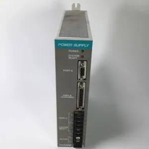
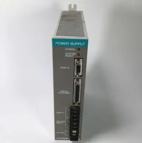
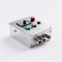
RELIANCE ELECTRIC WR-D4001-A is a digital I/O control module whose core functions are to realize accurate acquisition and stable control output of digital signals in industrial field. Specially designed for discrete control and equipment linkage scenarios of industrial automation systems, it can be seamlessly integrated into various PLC systems, DCS systems and industrial control platforms, providing reliable digital signal interaction support for scenarios such as mechanical equipment automation, production line process control and equipment condition monitoring.
Adopting an industrial-grade reinforced hardware architecture and compact design, this product features fast signal response, outstanding anti-interference capability and wide compatibility. It is widely used in fields including mechanical processing, auto parts production, chemical auxiliary control, food packaging production lines and warehousing and logistics sorting systems. It can work collaboratively with Reliance AutoMax series modules, Rockwell ControlLogix/CompactLogix series PLCs and third-party industrial control equipment, serving as a key component for achieving precise digital quantity control in industrial automation systems.
II. Functional Features
High-Response Digital I/O Signal Interaction
Equipped with multiple standardized digital I/O channels, it supports two-way coordination of Digital Input (DI) and Digital Output (DO). It can accurately collect status signals from devices such as limit switches, photoelectric sensors and travel switches, and output stable digital control signals at the same time to drive executive components like relays, contactors and solenoid valves, adapting to the discrete control requirements of multi-device linkage.
With excellent digital signal response performance, the input signal response time is ≤ 1ms and the output signal switching delay is ≤ 2ms. It can quickly capture the status changes of on-site equipment and execute control instructions, ensuring the real-time performance and operational accuracy of the control system.
Industrial-Grade Anti-Interference and Stability Design
Adopting a differential input structure and multi-stage electromagnetic interference suppression technology, with a built-in high-precision signal filtering circuit, it can effectively resist interference such as electromagnetic radiation, power grid fluctuations and contact jitter in industrial field, ensuring the stability and accuracy of digital signal transmission and adapting to complex industrial electromagnetic environments.
Selected industrial-grade long-life components and reinforced circuit layout have passed rigorous high-low temperature cycle, vibration and humidity tests, with excellent Mean Time Between Failures (MTBF) performance. It meets the requirements of 24/7 continuous operation in industrial field, featuring low failure rate and long service life.
Wide Compatibility and Flexible Integration
It is highly compatible with Reliance AutoMax series PLC systems and Rockwell Automation ControlLogix/CompactLogix series controllers, and supports standard communication protocols of third-party industrial PLC and DCS systems. It can be quickly integrated without large-scale modification of the existing control architecture, reducing system upgrade and adaptation costs.
Supporting dual-type input signals (NPN/PNP) and dual-mode output (relay/transistor), it can directly connect to various industrial digital devices and adapt to executive components with different load characteristics, featuring strong versatility and flexible adaptability to diversified industrial control scenarios.
Convenient Installation and Operation & Maintenance Optimization
The compact structure design occupies small installation space, supports 35mm standard DIN rail mounting or panel embedded mounting, and realizes quick assembly and disassembly through standard card slots and fixing screws, reducing on-site construction difficulty and time cost.
The panel is equipped with multiple groups of status indicator lights to feed back the module's power status, signal validity of each channel and fault information in real time, facilitating on-site personnel to intuitively troubleshoot problems; it adopts screw-type or spring-type terminal block design, with firm wiring and simple operation, improving wiring efficiency and connection reliability.

III. Technical Parameters
IV. Working Principle
The core working logic of RELIANCE ELECTRIC WR-D4001-A is "Digital Signal Acquisition → Signal Filtering → Logic Interaction → Control Output → Status Feedback", with the specific process as follows:
Digital Signal Acquisition: Connect to industrial on-site sensors (such as photoelectric sensors and limit switches) through digital input channels to collect digital signals (high/low level) such as equipment operating status and position detection. It automatically adapts to two input types (NPN/PNP) without additional hardware adjustment.
Signal Filtering: The collected original digital signals are processed by the built-in multi-stage filtering circuit to filter out clutter signals such as spike interference and contact jitter in industrial field, outputting stable digital signals, avoiding system false triggering caused by interference and ensuring the reliability of signal acquisition.
Logic Interaction: The filtered stable digital signals are transmitted to the PLC/controller through the backplane bus or communication interface to participate in system logic operations; at the same time, it receives digital control instructions issued by the controller, parses the instruction content and prepares to execute corresponding output actions.
Control Output: According to the controller's instructions, output high/low level or switch signals through digital output channels to drive the action of executive components such as relays, contactors and solenoid valves, realizing control functions including equipment start-stop, process switching and interlock protection, adapting to the execution requirements of different load types.
Status Feedback: The module monitors the working status of each I/O channel (signal valid/invalid, output normal/fault) and its own operating status in real time, and feeds back to the controller/upper computer through panel indicator lights or communication interfaces, facilitating operators to grasp the equipment operating status in real time and quickly locate abnormalities.
V. Operation Guide
1. Installation Steps
Installation Environment
Install the module in a well-ventilated control cabinet free from strong electromagnetic interference, avoiding proximity to interference sources such as frequency converters, high-voltage busbars and high-power motors; control the ambient temperature within the range of -20℃~+60℃ and relative humidity of 5%-95% (non-condensing); keep away from dusty, oily, corrosive gas and humid areas.
Mechanical Installation
Adopt 35mm standard DIN rail mounting or panel mounting, fix the screws according to the dimensions of the module mounting holes with a mounting torque of 0.5~0.8N·m to ensure firm installation without loosening; reserve ≥ 3cm heat dissipation space between modules to avoid overheating caused by dense installation.
Check that the module has no appearance damage and the terminals are free from oxidation and deformation, confirm that the model (WR-D4001-A) meets the installation requirements; verify the compatibility of the supporting power module and controller to ensure system adaptation.
Wiring Operation
Turn off the main power supply of the control cabinet, and connect the power cable, input signal cable and output control cable according to the wiring diagram: distinguish the positive and negative poles of the power cable to ensure the voltage level is 24VDC±10%; connect the input cable to the signal output end of the sensor and wire it according to the sensor type (NPN/PNP); connect the output cable to the executive component and select the relay/transistor output channel according to the load characteristics.
After wiring, check the correctness of the circuit to ensure that the input/output channels correspond correctly, and the terminal screws are tightened to avoid signal abnormalities or equipment damage caused by poor contact; it is recommended to use shielded cables for digital signal cables, with the shield layer grounded at one end (grounding resistance ≤ 4Ω) to enhance anti-interference capability.
2. System Configuration
Parameter Initialization
Power on, the module starts automatically (start-up time ≤ 10 seconds). Connect to the module through PLC programming software or upper computer configuration tools, configure parameters such as input channel type (NPN/PNP), output channel load mode (relay/transistor) and signal filtering time to ensure matching with on-site equipment.
Configure interlock protection parameters: Set input signal trigger conditions and output signal action logic according to control requirements, and enable the channel fault detection function to ensure rapid response in case of abnormalities (such as output short-circuit protection and signal loss alarm).
Communication Configuration
If the module is connected to the controller through the bus, configure parameters such as bus address and communication baud rate to ensure normal communication with the controller; read the module equipment information and channel status through the configuration tool to verify communication stability.
3. Operation and Maintenance
Daily Operation
Before starting, check that the module power supply and signal lines are connected normally without loosening or short-circuit hazards; after power on, observe the panel status indicator lights to confirm that there is no fault alarm in each channel and the module is initialized normally.
During operation, monitor the status and signal changes of each I/O channel in real time through the upper computer, check the fault records regularly, and handle problems such as signal loss and output abnormality in a timely manner; it is prohibited to arbitrarily plug/unplug the module or modify core configuration parameters during operation.
Regular Maintenance
Weekly: Wipe dust on the module surface with a dry soft cloth, check the terminals for oxidation and heating marks, and confirm that the wiring is firm; observe the status of the indicator lights to troubleshoot potential faults.
Monthly: Back up module parameters through configuration tools; test the effectiveness of input/output channels, simulate sensor signals to verify the acquisition function, test the driving capability of output channels; check the stability of the power supply voltage.
Annually: Conduct a comprehensive inspection of the module, clean internal dust (operated by professionals), and check components for signs of aging and bulging; calibrate the channel response time to ensure performance meets requirements; contact Rockwell after-sales service for professional maintenance if necessary.
4. Common Fault Troubleshooting


 Contact Platform Support
 Help Center