Home > Electrical & Electronics > Electrical Control System > Woodward 8290-194 Electric Governor

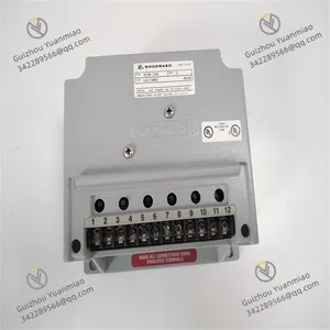
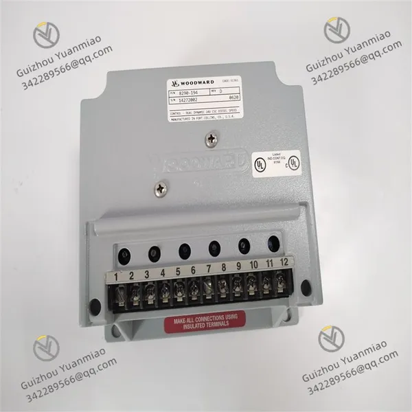
Woodward 8290-194 Electric Governor

Woodward 8290-194 Electric Governor photo-1
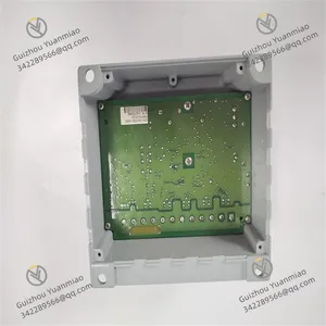
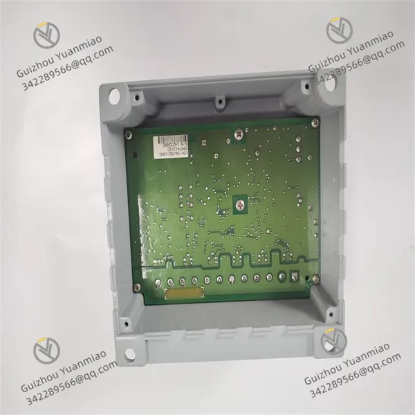
Woodward 8290-194 Electric Governor photo-2
Negotiable MOQ: 1 Piece (Price negotiable depending on order volume and customization)
Key Specifications
Get Latest Price
Material:
Other, Global universal model
Condition:
Other, Global universal model
Task:
Other, Global universal model

Payment & Shipping
Payment Methods:
Port of Shipment:
China
Delivery Detail:
Delivery time depends on order quantity.
Material Other, Global universal model
Condition Other, Global universal model
Task Other, Global universal model
Mathematical Model Other, Global universal model
Signal Other, Global universal model
Customized Non-Customized
Structure Other, Global universal model
Dimensions 263×58×28mm
Weight 4.3kg
Operating Temperature -20°C to 70°C
The Woodward 8290-194 is an Electric Governor (EPG) primarily used for precise speed control of diesel engines. The following is a detailed introduction:
Functional Characteristics
  • Flexible Signal Input: Can set equipment speed or load based on computer control signals of 4-20mA or 1-5Vdc, providing users with multiple options to meet different control requirements.

  • Multiple Working Modes: Features two working modes: isochronous regulation and droop regulation.

    • Isochronous regulation is mainly used for constant speed control, suitable for single-unit operation or collaborative work of multiple prime movers in independent power grids.

    • Droop regulation offers more control flexibility.

  • High Integration: Can be used in conjunction with a range of Woodward equipment, such as automatic power transfer switches, input-output controllers, generator load controllers, etc., to achieve comprehensive system control.

  • Rich Additional Functions: In addition to basic speed or load control, it also has functions such as synchronization or deceleration control, high-low speed adjustment, and fuel limiting for overspeed starting, further enhancing its performance and application scope.

  • High-precision Output Signal: The output signal provided by the controller is proportional to the fuel setting required to achieve the desired speed/load, ensuring precise control.

Technical Parameters
  • Dimensions: 263×58×28mm.

  • Weight: 4.3kg.

  • Operating Temperature Range: -20°C to 70°C.

  • Storage Temperature Range: -55°C to 105°C.

  • Power Supply: Suitable for 12Vdc or 24Vdc operation.

  • Output Shaft: Both ends of the output shaft are 0.375"-36 SAE serrated.

Application Scenarios
  • Suitable for various power equipment such as diesel engines, gas engines, steam turbines, or gas turbines, with wide applications in generator sets, compressors, pump stations, ships, locomotives, etc., effectively ensuring stable equipment operation within set ranges.

  • Particularly suitable for prime movers without mechanical drive or governor hydraulic oil supply and with low-mass, low-friction fuel connections.

8290-194 (2)

Working Principle
  1. Speed Monitoring: The magnetic pickup in the system is responsible for monitoring the engine speed. It generates an electrical signal proportional to the speed by sensing the magnetic field changes of the engine's rotating components, which is transmitted to the electronic speed control unit.

  2. Electronic Speed Control: The electronic speed control unit, i.e., the 8290-194 itself, receives the speed signal from the magnetic pickup and compares it with the preset speed value. When there is a deviation between the actual engine speed and the set speed, the electronic speed control unit calculates the amount needed to adjust the engine's fuel injection system based on the deviation's magnitude and direction, then outputs the corresponding control signal.

  3. Actuator Action: The control signal is transmitted to the Electric Actuator, which converts the electrical signal into mechanical movement through components like motors and gear transmission mechanisms. This physically adjusts the engine's fuel injection system, changes the fuel supply, and thus controls the engine speed. For example:

  • When the engine speed is lower than the set value, the actuator increases fuel supply to raise the speed.

  • When the engine speed is higher than the set value, the actuator reduces fuel supply to lower the speed.
    Through such closed-loop control, the Woodward 8290-194 accurately controls the diesel engine speed within the set range, ensuring stable operation under different load conditions. Additionally, the system supports functions like single-phase droop or isochronous control to meet diverse application needs.

Common Faults and Solutions for Woodward 8290-194I. Actuator No Response or Abnormal Action
  1. Power-related Faults
  • Fault Phenomenon: The actuator does not move, and indicator lights are off.

  • Possible Causes:

    • DC power supply is not connected or voltage is abnormal (standard voltage is typically DC 24V±10%).

    • Power line short circuit, open circuit, or poor contact.

    • Internal power module burnout (e.g., due to overvoltage or overcurrent damage).

  • Solutions:

    • Use a multimeter to check the input power voltage and confirm normal power supply.

    • Inspect power cable connections and replace damaged cables or connectors.

    • If the power module fails, contact professionals to replace the module

  • Abnormal Input Signal
    • Fault Phenomenon: The actuator does not respond to the controller signal.

    • Possible Causes:

      • The controller (e.g., Woodward 5500 series) does not output signals (4-20mA or PWM signals).

      • Signal cable is broken, has poor contact, or is affected by electromagnetic interference.

      • Actuator signal input impedance mismatch (e.g., standard impedance 250Ω is altered).

    • Solutions:

      • Use an oscilloscope or multimeter to check if the controller output signal is normal.

      • Replace with shielded signal cables, route them away from power cables to avoid interference.

      • Check signal terminal wiring to ensure impedance matching

  • Hydraulic System Faults
    • Fault Phenomenon: The actuator piston does not move or moves slowly.

    • Possible Causes:

      • Hydraulic oil source pressure is insufficient (standard working pressure range is typically 1.4-6.9 bar).

      • Hydraulic oil circuit blockage (e.g., contaminated filter element, sedimentation of oil impurities).

      • Proportional solenoid valve jamming or coil burnout (unable to control hydraulic oil flow direction).

      • Cylinder seal aging causing oil leakage, preventing pressure buildup.

    • Solutions:

      • Check hydraulic pump pressure, clean or replace the hydraulic oil filter element (recommended to use ISO VG 32 anti-wear hydraulic oil).

      • Disassemble the proportional valve, clean the valve core, and check coil resistance (replace if abnormal).

      • Replace cylinder seals, inspect and repair oil leakage points.

    8290-194 (1)

    II. Displacement Deviation or Out-of-Tolerance Adjustment Accuracy
    1. Feedback System Faults
    • Fault Phenomenon: The actual actuator displacement does not match the input signal, with deviation exceeding ±0.5% of full scale.

    • Possible Causes:

      • LVDT (Linear Variable Differential Transformer) sensor is offset or damaged, causing abnormal feedback signals.

      • LVDT cable is broken, has poor contact, or feedback signal is interfered (e.g., poor grounding).

      • Mechanical linkage is loose, leading to displacement transmission errors (e.g., loose linkage to fuel valve connection).

    • Solutions:

      • Use a multimeter to detect LVDT feedback voltage (e.g., 0-10V or 4-20mA), and recalibrate or replace the sensor if abnormal.

      • Check cable connections and re-ground, use shielded wires to reduce interference.

      • Tighten mechanical linkages to ensure installation error ≤0.5mm and axis parallelism

  • Closed-loop Control Abnormalities
    • Fault Phenomenon: The system continuously adjusts but cannot reach the target displacement, or oscillation occurs.

    • Possible Causes:

      • Incorrect controller parameter settings (e.g., mismatched PID adjustment parameters).

      • Air in the hydraulic system causes action lag or fluctuation.

      • Mechanical limit device jams, restricting normal piston movement.

    • Solutions:

      • Reconfigure controller parameters and optimize PID gains to match actuator response characteristics.

      • Degas the hydraulic system (e.g., loosen the exhaust valve until oil flows continuously).

      • Check if mechanical limits are loose or deformed, repair or replace limit components

    III. Abnormal Noise or Vibration
    1. Mechanical Component Issues
    • Fault Phenomenon: The actuator emits unusual noise or severe vibration during operation.

    • Possible Causes:

      • Loose installation bolts cause resonance between the actuator and the base.

      • Linkage or piston components are worn, with excessive clearance, causing impact during movement.

      • Fuel valve jams, requiring the actuator to overcome extra resistance.

    • Solutions:

      • Tighten all installation bolts and check if flange or bracket installation is secure.

      • Disassemble mechanical transmission components and replace worn bearings, linkages, etc.

      • Check if the fuel valve is jammed, clean impurities in the valve body or repair the valve core

  • Hydraulic System Issues
    • Fault Phenomenon: The hydraulic circuit emits a "buzz" or vibrates.

    • Possible Causes:

      • Insufficient hydraulic oil or air mixing in the oil (oil emulsification, obvious bubbles).

      • Proportional valve core wear causes hydraulic shock or unstable flow.

      • Hydraulic pipeline is not firmly fixed, causing vibration during fluid flow.

    • Solutions:

      • Supplement hydraulic oil and degas, check if the oil tank seal is good.

      • Replace the proportional valve or grind the valve core to ensure stable hydraulic flow.

      • Reinforce hydraulic pipelines to reduce fluid vibration effects

    IV. Emergency Protection Function Failure
    1. Manual Adjustment Failure
    • Fault Phenomenon: When the electrical control system fails, the manual adjustment knob cannot drive the fuel valve.

    • Possible Causes:

      • Manual override mechanism jams (e.g., rusted gears/screws or foreign matter blockage).

      • Mechanical limit device is locked, preventing manual adjustment.

    • Solutions:

      • Disassemble the manual adjustment mechanism, clean rust or foreign matter, and apply lubricating grease.

      • Check if the mechanical limit is in the released state and adjust the limit position

  • Mechanical Limit Failure
    • Fault Phenomenon: Piston over-travel, excessive opening or closing of the fuel valve.

    • Possible Causes:

      • Mechanical limit bolts are loose and displaced.

      • Limit stops are worn or broken, losing their blocking function.

    • Solutions:

      • Readjust and lock the limit bolt position to ensure the piston stroke is within 12.7mm.

      • Replace damaged limit stops and check the integrity of the mechanical structure

    V. Environment Adaptability-related Faults
    1. Performance Abnormalities Caused by High/Low Temperature
    • Fault Phenomenon: In environments below -40°C or above +85°C, the actuator moves slowly or malfunctions.

    • Possible Causes:

      • Hydraulic oil viscosity increases at low temperatures, reducing fluidity; oil oxidizes and deteriorates at high temperatures.

      • Electronic components are affected by temperature, such as capacitor failure or abnormal chip operation.

    • Solutions:

      • Replace hydraulic oil with appropriate viscosity according to ambient temperature (e.g., use antifreeze hydraulic oil in low-temperature areas).

      • Install heat insulation or heating devices for the actuator to ensure the working temperature is within -40°C~+85°C.

  • Protection Level Failure
    • Fault Phenomenon: Dust or liquid intrusion causes internal component short circuits or jams.

    • Possible Causes:

      • Aging or falling off of the housing sealing strip, reducing IP65 protection performance.

      • Waterproof connectors at wiring ports are loose and not properly sealed.

    • Solutions:

      • Replace the sealing strip and check the tightness of each housing joint surface.

      • Re-tighten waterproof connectors and apply waterproof glue if necessary.

    Product Tags: 8290-194 , PCD231B101 , GFD563A102

    Send Inquiry to This Supplier

    * Message
    0/5000

    Want the best price? Post an RFQ now!
    Verified Business License
    Business Type
    Trading Company
    Year Established
    2014
    Factory Size
    1,000-3,000 square meters
    Product Certifications
    SA8000