Material
Other, Global universal model
Condition
Other, Global universal model
Task
Other, Global universal model
Mathematical Model
Other, Global universal model
Signal
Other, Global universal model
Customized
Non-Customized
Structure
Other, Global universal model
Operating Temperature
-40℃~+70℃
Relative Humidity
5%-95% (non-condensing)
I. Product Overview
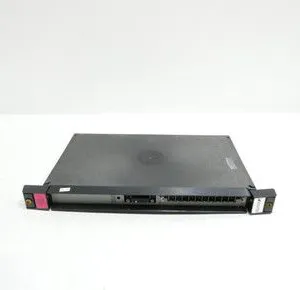
RELIANCE 0-57405-C is an analog I/O driver module whose core function is to achieve accurate acquisition, conversion and control output of analog signals in industrial field. Specially designed for pairing with PMI drives, it can also be seamlessly integrated into industrial automation systems and DCS systems, providing reliable signal interaction support for scenarios such as process control, mechanical equipment control and energy monitoring.
Adopting a robust industrial-grade housing package and compact design, this product features high reliability, high signal accuracy and easy integration. It is widely used in fields including chemical process control, pharmaceutical production, food processing, mechanical equipment automation, energy monitoring and environmental monitoring. It can work collaboratively with AutoMax series processor modules, memory modules, Ethernet interface modules, etc., and serves as a key component for realizing analog signal processing in industrial automation systems.
II. Functional Features
Multi-channel Analog Signal Acquisition and Output Capability
Equipped with 10 I/O circuit channels, it supports two-way interaction of analog signals. It can accurately collect analog signals output by sensors such as temperature, pressure, flow and liquid level sensors, and provide stable analog control output at the same time, meeting the requirements of multi-parameter monitoring and multi-device control in industrial field.
Adopting advanced analog signal processing technology, it features high signal acquisition and output accuracy as well as strong stability. It can effectively suppress electromagnetic interference in industrial field, ensure the accuracy of signal transmission, and provide reliable data support for control system decision-making.
Exclusive Adaptation to PMI Drives and System Compatibility
Specially designed for PMI drives, it realizes seamless connection with PMI drives through the RS-232 female connector on the panel (marked "TO PMI"), ensuring efficient transmission of drive control signals and execution of instructions, and is suitable for drive control scenarios of industrial motors, pumps, valves and other equipment.
It can be integrated into AutoMax card storage racks, working collaboratively with same-series processor modules, memory modules, power modules, Ethernet interface modules, etc. Meanwhile, it is compatible with mainstream DCS systems in the field of industrial automation, and can be integrated into existing control systems without large-scale modification.
Industrial-grade Structural Design and High Reliability
Adopting a robust metal housing package, the internal circuit board is equipped with top and bottom mounting brackets, which are fixed to the rack with screws, ensuring firm installation and excellent vibration resistance. The open bottom design facilitates air circulation, improves heat dissipation efficiency and ensures long-term stable operation.
Selected industrial-grade high-quality components have passed rigorous environmental adaptability tests. They can maintain stable performance even in complex industrial environments, meet the requirements of 24/7 continuous operation in industrial field, and feature long average service life and low failure rate.
Convenient Installation and Configuration Experience
The compact design occupies small installation space. It can be directly inserted into the card slot of AutoMax card storage rack and fixed with two screws, making installation and disassembly operations simple, and reducing on-site construction difficulty and time cost.
The panel is equipped with an "OVERSPEED CALIBRATION" LED indicator light, which intuitively feeds back the module's overspeed calibration status and operation status. It is provided with P3 terminal block and P4 RS-232 female connector, with clear wiring methods, facilitating on-site wiring and equipment connection.

III. Technical Parameters
IV. Working Principle
The core working logic of RELIANCE 0-57405-C is "Signal Acquisition → Signal Conversion → Data Transmission → Control Output → Status Feedback", with the specific process as follows:
Signal Acquisition: Connect to industrial field sensors (such as temperature and pressure sensors) through the P3 terminal block to collect analog signals. The collected signals are amplified and filtered by the signal conditioning circuit inside the module to remove interference clutter.
Signal Conversion: The conditioned analog signals are converted into digital signals through Analog-to-Digital Conversion (ADC) and transmitted to the AutoMax PLC processor module for logic operation and data analysis.
Data Transmission: If it is necessary to drive the PMI drive, the control instructions generated by the processor module are transmitted to the PMI drive through the module's RS-232 interface (TO PMI), realizing precise control of motors, pumps and other equipment. Meanwhile, the module can receive feedback signals from the drive.
Control Output: According to the instructions of the processor module, the digital control signals are converted into analog output signals through internal Digital-to-Analog Conversion (DAC), and sent to external equipment such as actuators and control valves through the P3 terminal block to execute corresponding control actions.
Status Feedback: The "OVERSPEED CALIBRATION" LED indicator light on the panel feeds back the module's overspeed calibration status and operation status in real time. When an abnormality occurs, the fault can be quickly identified to facilitate operation and maintenance troubleshooting.
V. Operation Guide
1. Installation Steps
Installation Environment
Install the module in a well-ventilated control cabinet free from strong electromagnetic interference, avoiding proximity to interference sources such as frequency converters and high-voltage busbars. Ensure the installation location is dry, free from dust, oil stains and corrosive gases, meeting the installation environment requirements for industrial-grade equipment.
Mechanical Installation
Align with the card slot of the AutoMax card storage rack, insert the module smoothly to ensure the module is fully fitted with the internal interface of the rack. Fix the module to the rack with two screws through the top and bottom mounting brackets on the module panel, with moderate tightening torque to ensure firm installation without loosening.
Check that the module has no appearance damage and the connectors are free from deformation and oxidation. Confirm that the model (0-57405-C) and part number meet the installation requirements. Verify that the supporting components such as the rack power module and processor module are connected normally.
Wiring Operation
Turn off the main power supply of the control cabinet, and connect the lines in accordance with wiring specifications: connect the P3 terminal block to sensors and actuators, distinguishing signal positive/negative poles and signal lines; connect the RS-232 female connector (TO PMI) to the corresponding interface of the PMI drive, ensuring firm wiring without poor contact.
After wiring, check the correctness of the lines to avoid short circuit or reverse connection. Inspect all connection points for no looseness, and tighten the terminal screws to ensure stable signal transmission.
2. System Configuration
Parameter Initialization
After power on, connect to the module through AutoMax PLC configuration software. Set parameters such as signal range, acquisition frequency and output threshold according to the requirements of field equipment, ensuring matching with the parameters of sensors, actuators and PMI drives.
Calibration Operation
Use the "OVERSPEED CALIBRATION" function on the panel to perform overspeed calibration, ensuring the accuracy of module signal acquisition and output. During the calibration process, observe the status of the indicator light until the calibration is completed and the status is normal.
Linkage Configuration
If integrated into a DCS system, configure the communication parameters between the module, processor module and upper computer to ensure normal data interaction. Test the linkage function with the PMI drive to verify the reliability of control instruction transmission and feedback signal reception.
3. Operation and Maintenance
Daily Operation
Before starting, check the installation and fixation of the module and the status of line connections to confirm no looseness or abnormality. After power on, observe the LED indicator light on the panel to confirm the module starts normally without fault prompts.
During operation, monitor the signal data collected by the module and output status in real time through the upper computer. Check the operation log regularly, and handle signal abnormalities or equipment faults in a timely manner. It is prohibited to arbitrarily plug/unplug the module or modify core parameters during operation.
Regular Maintenance
Weekly: Wipe dust on the module surface with a dry soft cloth, check the connectors for oxidation and looseness, and ensure the heat dissipation channel is unobstructed.
Monthly: Verify the module parameter configuration, test the accuracy of signal acquisition and output. Check the connection stability with the PMI drive and processor module, and re-tighten the terminal screws if necessary.
Annually: Conduct a comprehensive inspection of the module, clean internal dust (operated by professionals), and check components for signs of aging. If the module fails, contact the supplier for repair or replacement with an alternative model.
4. Common Fault Troubleshooting


 Contact Platform Support
 Help Center