


 Contact Platform Support
 Help Center
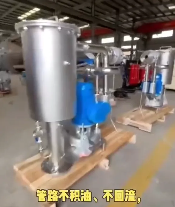
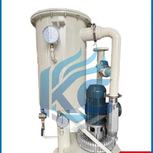
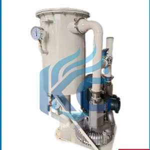
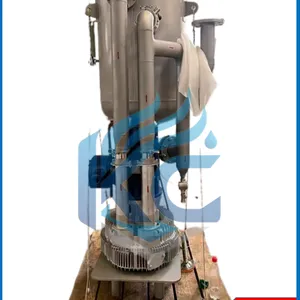
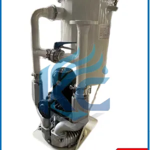
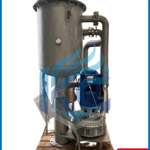
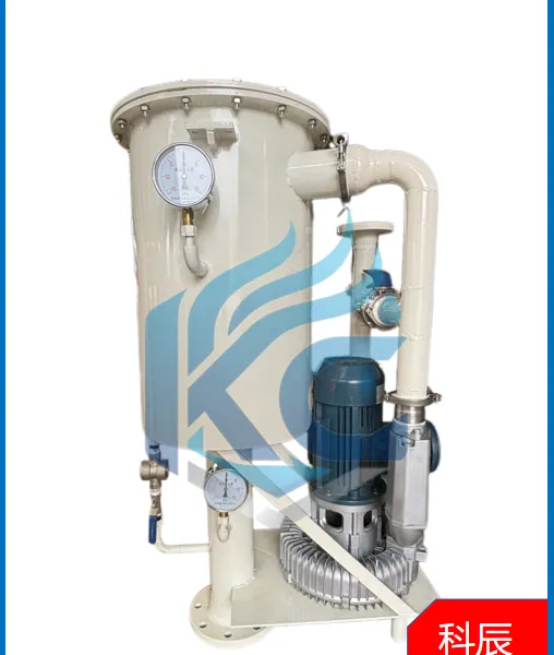
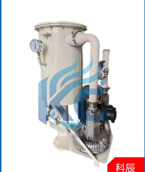
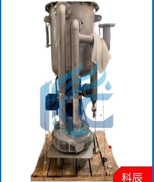
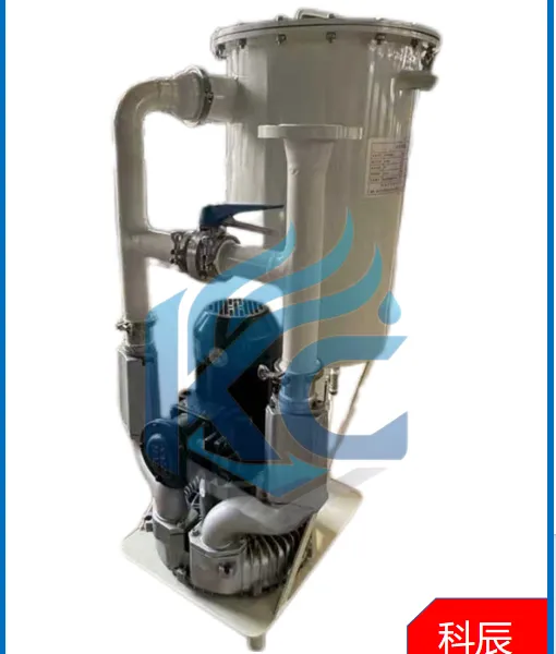
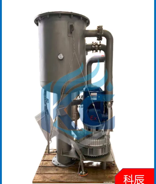
Blower Oil Mist Separator for Vacuum Pump System
Product Spotlights







Related Products
-
 Fan Oil Mist Separator Oil Mist Removal for Fan Pipelines in Chemical, Coating, Rubber and Plastics IndustriesUS$ 800 - 1000MOQ: 1 Piece
 -
Flanged Small Water-Gas Separator for Vacuum Pump InletUS$ 800 - 1000MOQ: 1 Piece
-
Portable Oil Purifier for Power Plant Lubricating OilUS$ 800 - 1000MOQ: 1 Piece
-
Movable Circulating Oil Purifier for On-site ConstructionUS$ 800 - 1000MOQ: 1 Piece
-
High Precision Coalescence Separation Vacuum Oil PurifierUS$ 800 - 1000MOQ: 1 Piece
Brand: MT
Model: MGF---/
Working Principle: Coalescence Separation
Function: Oil Mist Separation
Type: Vertical
Working Pressure: -2~7 kPa
Applicable Temperature: <60℃
Main Material: Q235B, 304
Connection Form: Flange
Installation Position: Top of Oil Tank
Oil Removal Efficiency: >99%
Filtration Precision: <1μm
Design Standard: GB/T 5450 Test Method for Oil Mist in Gas
Application Scope: Oil fume discharge locations such as turbine lubricating oil stations and gear oil tanks.
Working Principle:
The MFF oil mist separator adopts coalescence separation technology as the core to remove oil mist from oil fume. Integrating impurity filtration and oil mist separation functions, the unit effectively removes particulate impurities, atomized oil fume and water vapor in gas. It adopts multi-stage filtration technology consisting of three separation stages: centrifugal primary separation, motion impact secondary separation and coalescence separation. Specially developed for lubrication systems, this equipment can efficiently eliminate oil mist and water vapor inside oil tanks to avoid secondary environmental pollution, significantly reduce lubricating oil consumption, and maintain zero pressure inside the oil tank in case of accidental blower shutdown.
The coalescence separation filter element is assembled with imported materials of various materials and properties. MT adopts coalescence media supplied by well-known overseas manufacturers including Lydall, H&V and SINOMA to guarantee stable performance. Different materials feature distinct filter gaps, surface tension properties and lipophilic/hydrophilic, oleophobic/hydrophobic characteristics. The combined application of diverse materials realizes filtration, coalescence and separation, ensuring outstanding separation performance.
Screening In addition to oil fume, oil mist contains various solid particles. Solid contaminants impair coalescence and separation efficiency and drastically shorten filter service life. MT coalescence filter elements are equipped with a depth filtration layer upstream of the coalescence layer. Deep filtration of gas prior to entering the coalescence filter greatly extends the service life of the filter cartridge.
Coalescence Coalescence is achieved based on the surface tension of the medium. The coalescence layer features a multi-layer winding structure composed of 3 to 4 types of media. Specially designed air channels promote the transformation of tiny oil aerosols into large oil droplets. Combining core technologies analogous to Pall standards, MT coalescence filter elements deliver high throughput and powerful coalescence capacity. They can operate continuously under harsh conditions with saturated oil mist and possess advantages unmatched by traditional sintering and felting processes.
Separation Gas passing through the coalescence filter enters the separation layer. Driven by airflow, large oil droplets collide with the separation layer due to lipophilic and oleophobic properties. Large oil droplets settle to the bottom of the vessel under gravity.
Oil Recycle Oil separated from oil fume by the blower is clean enough for direct reuse. The equipment is fitted with an oil return pipeline to convey recovered oil back to the oil tank. A dedicated drain pipeline is reserved and extends below the low liquid level.
Note: 200/80 refers to the flange size of the inlet and outlet of the oil mist separator. The specific flange dimensions and standards can be customized according to customer requirements.
II. Technical Conditions for Selection Reference
Working Medium: Oil-laden air Operating Condition: Mounted on the top of oil station, suitable for indoor and outdoor operation Operating Rotational Speed: 2900 rpm System Inlet Pressure: -0.2 ~ -0.5 kPa; Allowable Negative Pressure: 10 kPa Power Supply: 380V, 50Hz, 3-phase
It adopts coalescence separation to remove oil mist with oil mist removal efficiency ≥99.98%, which can eliminate oil droplets contained in oil fume. Pressure gauges are installed on the upper cylinder and lower air inlet of the oil fume extractor. Bypass pipelines are arranged at the inlet and outlet of the oil exhaust fan and connected with manual globe valves to adjust the air delivery volume of the fan, ensuring zero inlet pressure of the separator when the fan stops.
Selection Instructions for MFF Oil Mist Separator
Oil station flow below 300 L/min: Motor power 1.1 kW
Oil station flow 300 ~ 600 L/min: Motor power 1.5 kW
Oil station flow 600 ~ 1200 L/min: Motor power 2.2 kW
Oil station flow 1200 ~ 1800 L/min: Motor power 4.0 kW
Oil station flow 1800 ~ 2400 L/min: Motor power 5.5 kW
Oil station flow above 2400 ~ 3000 L/min: Motor power 7.5 kW
The above specifications are common selections for oil mist separators. For large-flow oil systems (flow over 3000 L/min), please consult our technical staff. Larger models shall be adopted for gearbox separators and compressors equipped with sealing buffer gas.
Air Flow - Power Selection:
Example: MFF180-0.75-150/80-SS 180 – Air flow (m³/min) 0.75 – Matched motor power 150/80 – Inlet and outlet connection sizes of oil mist fan SS – Stainless Steel (CS – Carbon Steel)
Special requirements (such as SS316L stainless steel, copper-free materials, etc.) shall be specified in the technical agreement.
Working Principle Diagram:

Send Inquiry to This Supplier


You May Also Like
-
Box-type High Precision Oil Purifier for Hydraulic OilUS$ 800 - 1000MOQ: 1 Piece
-
Large Flow High Viscosity Oil Purifier for Waste Oil RegenerationUS$ 800 - 1000MOQ: 1 Piece
-
High Solid Content Oil Purifier for Metallurgical Rolling OilUS$ 800 - 1000MOQ: 1 Piece
-
Ultra-precision Oil Purifier for Wind Power Gearbox Lubricating OilUS$ 800 - 1000MOQ: 1 Piece
-
Plate and Frame Oil Purification Equipment for Rolling Oil Clarification FiltrationUS$ 800 - 1000MOQ: 1 Piece
-
Hand-push LUC Oil Filter Cart for Industrial Lubricating OilUS$ 800 - 1000MOQ: 1 Piece
-
SLUC Double-cartridge Bypass Oil Filter Cart for Machine Tool Lubrication SystemUS$ 800 - 1000MOQ: 1 Piece
-
OF7 Hand-held Filtration Equipment for On-site Micro FiltrationUS$ 800 - 1000MOQ: 1 Piece
-
Low-noise Industrial OF5 Bench Oil Filter for Solid Contaminant RemovalUS$ 800 - 1000MOQ: 1 Piece
-
OFU10 High-efficiency Oil Filter for Solid Contaminant Removal of Hydraulic Pump StationUS$ 800 - 1000MOQ: 1 Piece


